The invention of stereo reproduction from a single groove is often attributed to Bell Telephone Labs and Blumlein but it would appear that they were pre-empted by about a decade. Samuel S. Waters of Washington DC was granted patent No 1520378 on 23rd December 1924 (application dated 3rd July 1920) which describes a mechanico/acoustic transducer for independent operation from each groove wall. The arrangement anticipated by 30 years the couplers between stylus and crystal used in stereo crystal pickups.
To get the best interface between a stylus and a record, it is best to replay the record in exactly the same manner in which the master was cut, ie; tangentially, 15° from the normal, although some high-spec cartridges will use a far higher angle. Radial arms will obviously, because of the trajectory induced in the stylus' travel, introduce distortion that remains of intense discussion, but nevertheless satisfies the majority of tastes. To obtain carrier-channel information, or improved high frequency performance, a defined stylus edge is required, and a decent tangential deck.
Tangential arms will not only reduce radii errors by at least an order of magnitude, but will reduce stylus and record wear. A high quality record deck with a radial arm giving a stylus to pivot mass (Me) of 9gm will exert on a record of some 650 grooves (counted on the radius, a record having only two continuous grooves, one on each side) played once a week for five years some 315,900 ergs, enough to lift a 63kg man 5cm off the ground. A tangential arm offering a Me of 4gm will exert 140,400 ergs, or 56% less. Useful examples are the Beogram 6000, Revox B795 and the compact Technics SL-10. Useful DIY references are posted by Traddles.
If radial arms are used these should have a low-mass and low friction gimbal suspension. A very desirable feature is an auto-return at the end of the record and is considered essential for normal use. The Technics SL-Q2 is a good example. Arms like SMEs can be very nice to own but one can become tired by the sound of a stylus trapped in the last groove.
Some users mix 'n' match styli of one make for those of another without apparent detriment, in fact many decks giving satisfactory domestic or commercial service have been seen where the stylus fitted is neither of the same make or even compatible physical type. This does not surprise given that one 1990 catalogue offered in excess of 600 different types although most retailers could cover most needs with a range of, say, 40.
Some moving-coil/transformer combinations cost more than most would pay for an entire system. The same could be said about arms, the Odyssey Engineering RP1 tone-arm, for example, being available in any finish desired by the customer, including gold. Another type floated on silicone, while another (tangential) offering traversed the record on a pair of precision quartz rods. A Revox solution used magnetic suspension, whilst a topline Sony arm had sixteen motors in it. Putting this on an onyx plinth with a self-centring turntable before blowing a fortune on the best cartridge money can buy might impress some, but one still had to get up to change the record! One can then spend on a preamp what others will pay for a car, eg; Audio Research SP-11, Yamaha C-1, etc. Unfortunately, many of those seeking 'the best' simply spend money in order to express taste or flaunt resource, with no real benefit. Despite the use of teak, steel, aluminium, magnesium and carbon fibre, the author has yet to meet the individual who can differentiate, by hearing alone, between a choice of top-line tone arms, disregarding wiring issues. More recently, a deck intended for domestic use was priced at 5k. If the author ever seriously considered spending 18, 15 years later this had dropped to 50p). A decade later the 741 and, perhaps better, 748 ICs were 'ubiquitous'. Home construction, many found, was a way to obtain new and innovative technology cheaply. Below is the Plessey (1969?) design which must represent one of the earliest examples of IC op-amps being used in a 'hi-fi' preamp.
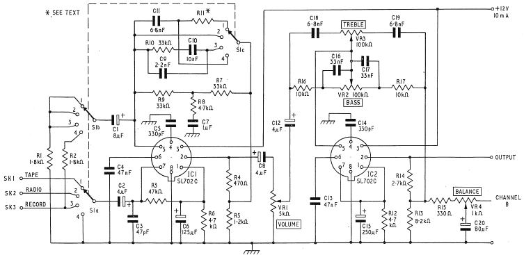
Notable is the additional switch wafer, compared to other approaches. Specs were surprisingly good and would withstand comparison today.
The Baxandall solution with switchable overall gain to accommodate differing depths of groove modulation that, to many, opitimises a practical ideal (data kindly supplied by Alister Sibbald).
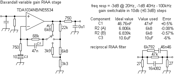
The addition of a buffer to prevent overloading the output filter is recommended and a higher value resistor between the switch wiper and the opamp output will reduce the possibilities of instability when the feedback path is momentarily open-circuited during switching if a make-before-break switch is unavailable.
An earlier house-publication intended to promote the use of opamps for audio (application Report B80, Texas Instruments Ltd) had given rise to some compact designs.

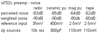
A popular DIY (PW Texan) amps' preamp intended for DIN outputs with rumble filter, improved RF filtering and tapehead eq values. The diagram above shows the input options available and not the 3-way input selection actually used in the Texan.
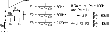
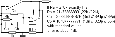
The supposed economy of employing two sets of switches in both the input and the eq feedback loop, instead of a dedicated low-level stage and higher-level buffers feeding a single switch set, led with use to excessive contact noise. Though popular with manufacturers, this approach should be avoided (see below). This problem was overcome in sophisticated layouts like that used for the '74 Lecson AC1 which used FETs and transistors for both switching signals and eq.
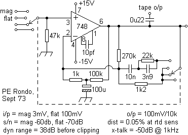
Almost identical, but less refined version for a later SQ system. The 270k resistor in the feedback loop, although part of the RIAA network, is permanently in circuit to reduce the switching transient caused by open-circuiting the feedback loop when using break-before-make push-button switches, thus producing a momentary, but startling, screeching. With higher tolerance capacitors the RIAA conformity could be improved, the Rondos' prototype giving a deviation of +6dB @ 60Hz and ±2dB over the rest of the range. These became a commercial 'standard', an identical circuit appearing in E. A. Parrs' 'How to use Op Amps' (Babani BP88, ISBN 0-85934-063-5, 1982). In subsequent builds, 748s have been replaced by TL070s and 741s by TL071s.
By adopting the DIN output standard (current-driven into a high impedance at low voltages) the matching power amplifiers had to have an unnecessarily high gain (>121) thus amplifying system noise commensurately.
A dual low-noise IC approach intended for hi-fi use. Compact constructions on stripboard using 35V tantalums could be fitted in record decks with benefits in respect of signal-to-noise. Most users particularly noted a reduction in mains hum.
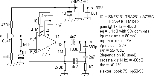
Note how output electrolytic is included in feedback path, a point considered important to some. At some users' requests, a later update used the HA12017.
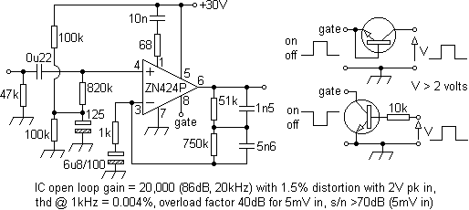
A design considered for a record deck whose arms' position gated the preamp on and off. Mechanical interface not proceeded with and therefore not used. Lower value feedback decoupling cap (6µ8F) suggested for rumble filter. IC output resistance 4k, decoupling required.
The next was intended to demonstrate 'the 'inverting-sawtooth' method for low t.i.d. measurements', "this circuit, in terms of traditional parameters, represents the current
state-of-the-art in i.c. RIAA".
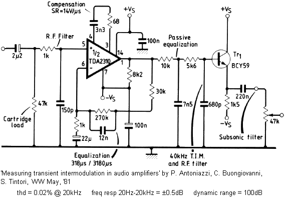
Note polarity of decoupling C on - rail.
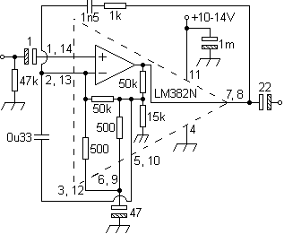
LM381 preamp ICs have appeared in a number of respectable designs, like the quadrophonic B&O; further down the page. Below, a LM382N implementation that probably ranks as that with the lowest possible component count utilising onboard resistor network, suitable for the most basic systems, compared to later LM387 build with a more considerate eq (with built-in rumble filter!) and dynamic range. Output coupling advised.
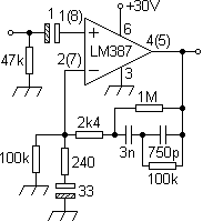
A mid-eighties design. With a gain of 271 at DC, LF contributions from the turntable or an off-centre record can become troublesome. Putting a stylus on a record played on a DC system can be more exciting than the actual music. A tantalum capacitor (normally 100µF) in series with the 1k resistor would negate the need for offsetting and AC coupling the next input stage (note eq values are identical to the those chosen for the Texan and Rondo seen above). However, smaller values used for input and output coupling would improve.
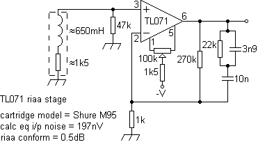
Such a minimalist approach can be detrimental to listening pleasure since additional system noise will invariably be manifest. An acknowledgement of the real world can be seen in the Technics SU-9070 below.
A later approach in a similar vein, that assumes a perfect record and turntable, with a DC gain of 1,010. Notwithstanding motor and bearing noise, use with a tangential deck will reduce modulations imposed by radial arms with light tracking forces.
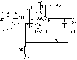
A realisation of some of the points made above, using higher than usual impedances in the feedback network, allowing the use of close tolerance, low temperature coefficent capacitors like mica or polystyrene types.
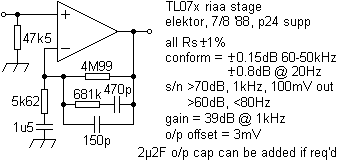
With high impedances like these thought can usefully be given to the overall screening of the circuit.
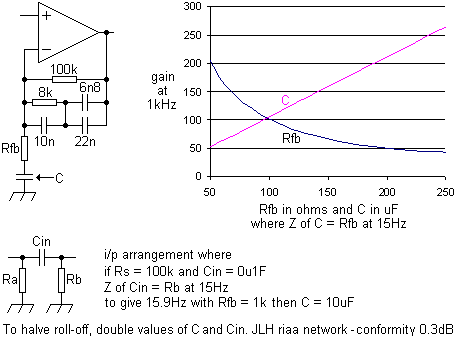
Basic feedback arrangement for a JLH design giving a close match. Personal preference would include input coupling and feedback decoupling caps. A good starting point, to give -3dB roll-offs, would be about 15Hz.
A Raytheon application intended for moving-coils (Jensen JE-34K-Dx transformer used on input, 13k resistor in series with 120pF across secondary). Concerns over input amplifier configuration but is that specified by data-sheet. Another opamp, the OP-47, was a decompensated OP-27.
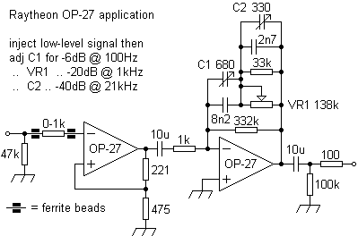
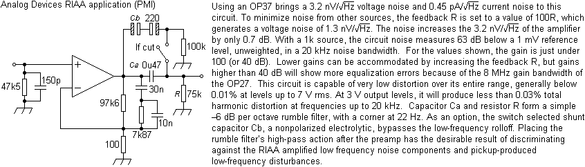
The Analog Devices OP37 (rev. B) datasheet has useful 'Comments on Noise' and the next application.
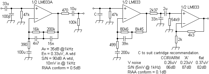
Two offerings from a National Semiconductor datasheet ('High-Performance Audio
Applications of The LM833'); a less critical arrangement (something similar being used in the tangential Beogram 3500/4500 and 6500) and details of a higher spec two-stage RIAA preamp (±0.1dB). The same component values are used in the LM4562 opamp datasheet (bar the latter which is not shown).
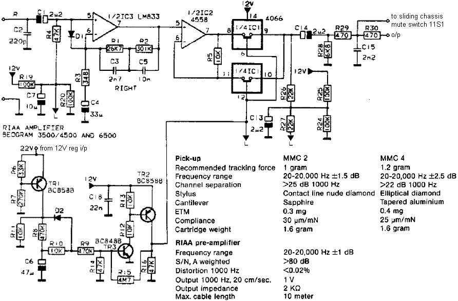
Another used in later B&O; tangential decks which included supply activated muting apart from mechanical switching.
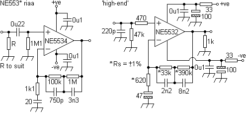
The NE5534 has been a personal favourite for audio over many years freeing up long hours of component matching for comparable or even better performance. On Semiconductors' AND8177/D application note gives a good range of designs, although be mindful of the numerous errors that it (Rev. 0) contains. The second example shown below is specified for a 'high-end' (2001) preamp kit.
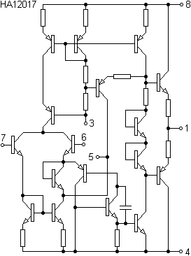
The HA12017 IC from Hitachi reduced board space considerably (SIL package). Reference version, using 14.8sq" (97sq cm) of PCB (resistors flush with board) for a stereo pair.

The manufacturers' suggestion is for a bass roll-off at 3Hz. As related elsewhere, a 15Hz corner will reduce turntable noise. Compare to another manufacturers' application below.
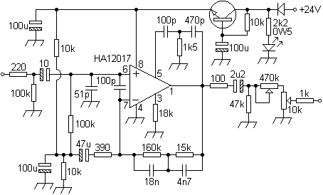
A stereo arrangement of the above, with regulator (onboard, not shown), will fit on less than 4sq" (26sq cm) of stripboard comfortably (resistors upright). Noise quoted -114dBV with ±5% carbon resistors. Regulation with ripple filtering effectively reduces supply hum, giving a lower noise floor and greater dynamic range. To improve, use metal-film ±1% resistors, input and output coupling caps can be bi-polar (input cap can be reduced), with additional bi-polar types in parallel with the other electrolytics. Supply can be increased to 48V (adjust Rd - pin 3 to gnd). Feedback rolls off at 8.6Hz. Compares subjectively with far more complex designs.
The only preamp design seen that used the HA12017 as an 'opamp' was the Armstrong 730. Here, three per channel were used, one as an RIAA stage (as per reference example above with a higher bass roll-off - 22.5Hz) and two as gain-blocks and supersonic filters giving performance considered exceptional at the time.
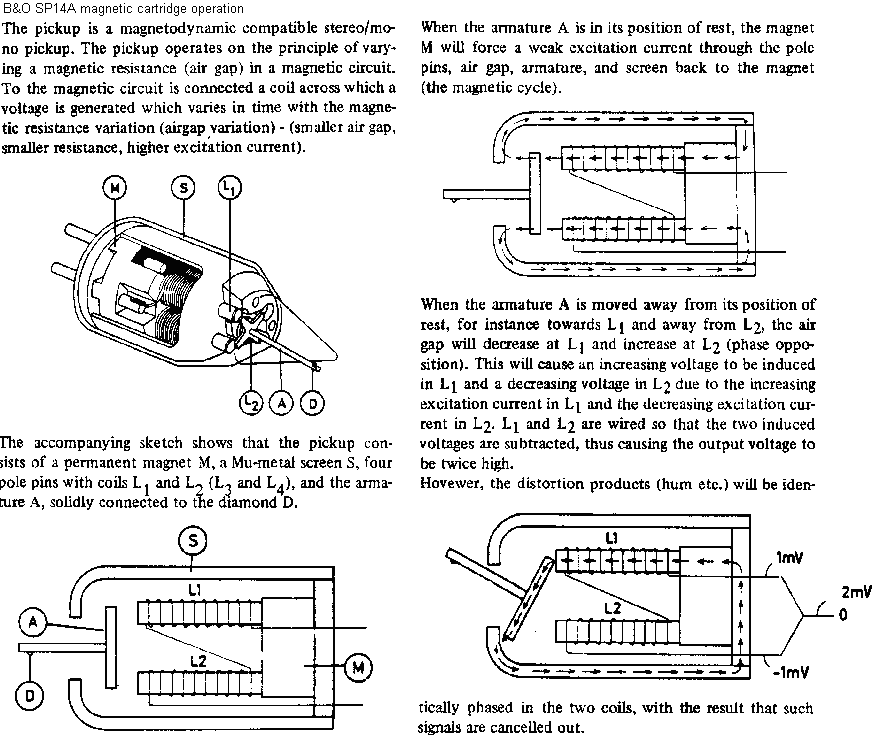
The next was mounted in the ground-breaking Beogram 6000 tangential deck (exploded views of which can be found here) and intended to be driven by the B&O; MMC 6000, and later MMC 20CL, cartridges fitted with a Pramanik-cut diamond. This was a (RCA/JVC) class A pickup deviating by ±10dB at 50kHz, class B gave 15 and class C 20. The CD4 difference signals (up to 45kHz) were taken direct from the opamp output, VR1 used to set decoder threshold levels. AC couple the output into a high impedance to avoid loading the output filter (another LM381 RIAA stage).

CD4 discs were cut using the 'Neutrex' technique, a development of the RCA Dynagroove system, intended to improve the tracking of high-frequency modulations. The sum signals (F+R, L or R) extended to some 15kHz and the difference signals (F-R) centred around 30kHz (-10kHz, +15kHz -19dB wrt sum). From 0 to 20kHz the pickup signal must be de-emphasised according to RIAA whilst the 20kHz to 45kHz range must be frequency and phase demodulated, then ANRS noise compensated, following which they are fed through a matrix to restore the original front and rear signals.
The Beogram 4000/6000 series tangential decks, it is felt, were truly beautiful and desirable objects, especially if finished in rosewood. The earlier models' tone arm was able to track outwards despite this having no relevance to a 'normal' user. The later models were distinguished by control circuits built with discrete devices, rather than renumbered 7400 ICs and optical arm positioning, apart from being fitted with, or ready to accept, the CD4 decoder. Low ambient temperatures can stiffen the cantilevers' suspension producing decoder dropout.
Another concise arrangement that has seen some usage. Ideally used with the MMC 20EN cartridge, use with a non-B&O; cartridge may require additional capacitance on the input (some models fitted with 470k input resistor).
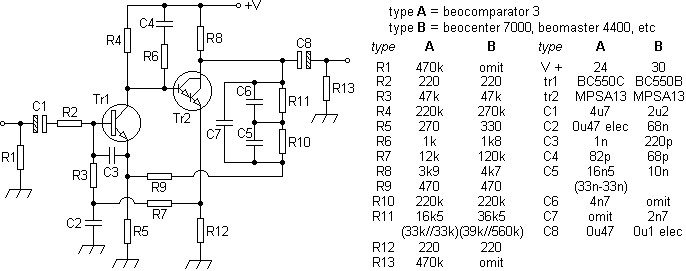
By contrast, a layout representative of some 'top-line' designs of similar vintage intended for more radial arms, which reminds one of the '73 Lohstroh and Otala power amplifier.
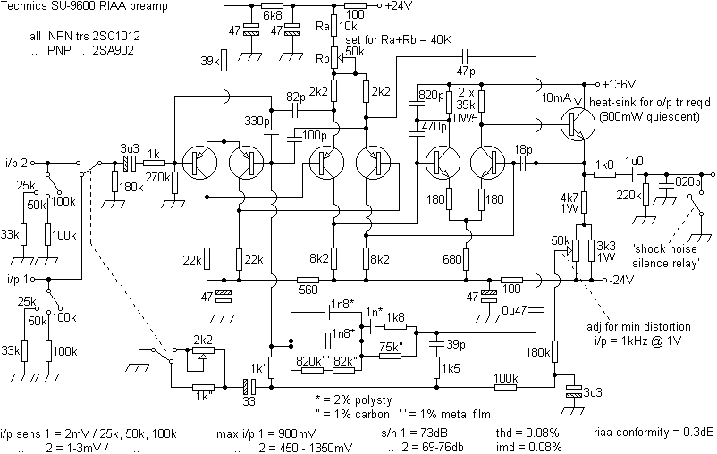
Note the supply voltages, giving some +56V at the output transistors' emitter. This DC component in the signal path must have given rise to the use of the 'shock noise silence relay', to short the output on power up. The name given to this relay is telling, 'shock noise' often being a feature of DC systems. Both the output stages' positive rails were fed by their own separate power supply. Large number of compensation capacitors employed.
High supply voltages, like the +100V and -110V used in the Yamaha C-1, were intended to increase the rated input and s/n ratio.
Whilst all the other models of Technics' tuner amps in one years' range utilised an IC (note use of hum filter),
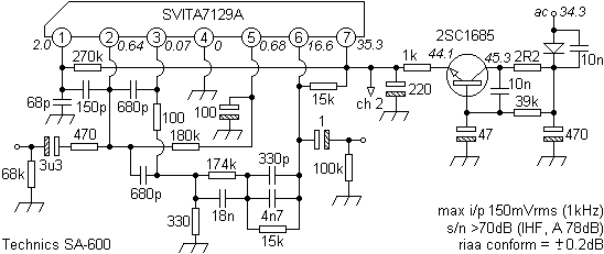
a higher model reverted to a discrete format giving better headroom, 5dB more signal to noise ratio and tighter RIAA conformity (compared to 1dB in some models).
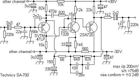
A more specialist Technics (SU-9070) approach with rumble filter, near identical feedback networks appearing in later models.
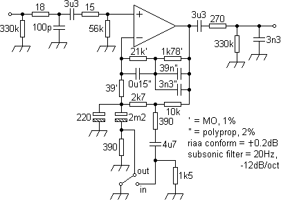
The input and output filtering is considered reasonable. Infrasonic or near-DC modulations are considered best excluded from a sound system from the outset as should RF. The output filter will reduce noise at higher frequencies.
Maintaining an emphasis on relatively complex DC biasing systems, regretable are the switch contacts before these, whose noise will only be amplified with the signal. Sensibly, AC coupling is employed on the outputs, features retained below.
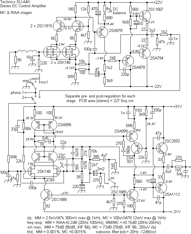
DC misalignments in the MC stage and the more complex amplifiers following these stages will result in the familiar 'shock noise'. Earlier designs were prone to drift by employing discrete rather than 'paired' devices. A nice design can result if inaudible parts of the spectrum are accommodated. However, a nicer and more efficient design might result from designing them out. Regardless the quality of the source, an increased component count can offer an increased rate of failure since there is more to go wrong. Personal preference has no objection to AC coupling for audio purposes, provided the inadequacies of electrolytics are understood. The same can be said about switch contacts.
The slightly earlier SU-V6, which has been in use by one user for thirty years with a boron-piped EPC-205C Mk3 cartridge on a SL-Q2 deck which still provides an excellent reference.
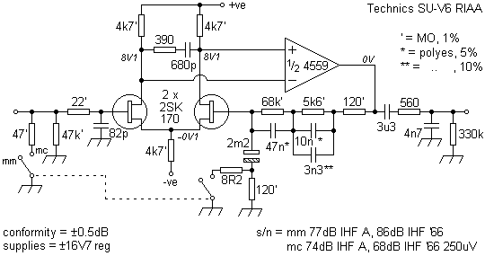
A similar arrangement, with bipolar input transistors, was used in the later Carver 4000t preamp (phono 1).
The later SU-A8 stereo DC control amplifier used paralleled input FETs in a configuration similar to that in the SU-C2000 which used an additional output opamp in what was described as a class AA preamp. Again, a similar arrangement, with bipolar input transistors, was used in the Carver 4000t preamp (phono 2). The regulated supply rails, apart from IC regulators, included ripple filters called a 'virtual battery' which used FETs to drive the series pass transistors. This unit had remote control.

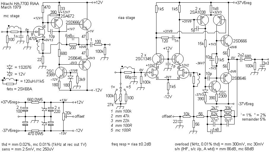
The Hitachi HA-7700 used FETs and, unfortunately, four sets of switches to select one of two phono inputs and the MM input impedance, allowing flexibility but deteriorating performance over time with wear. Coils are again used to improve the s/n ratio and crosstalk. The PA for this model can be found here.
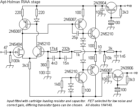
The Apt/Holman Preamplifier of the same year, influenced by Tom Holmans' work (subject to a number of patents) impressed a large following (data kindly supplied by Aren van Waarde) and was unusual by employing a differential input stage that used a FET and a bipolar device. Note use of hum filters. Output loading virtually identical to Quad 33 shown above.
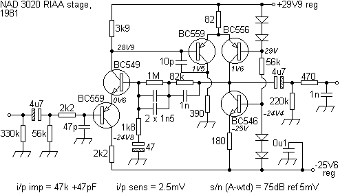
The NAD 3020s' RIAA stage (Holman?) used an interesting biasing arrangement, but the output then had to negotiate four sets of switch contacts before reaching the next stage, thus giving rise to noise.
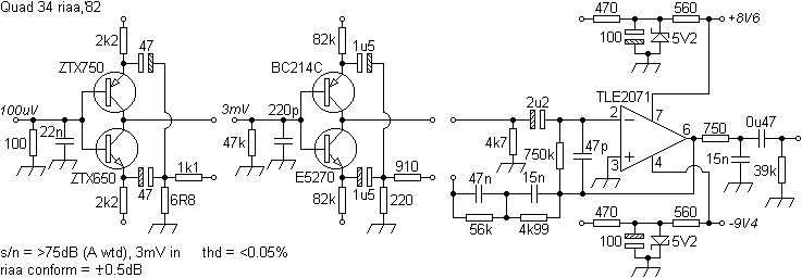
The slightly later eq stage from the Quad 34 which then fed a digitally switched input selector which has similarities to that used in the Crown IC-150A.
Another 'different' approach from the enigmatic Cyrus 1 amplifier, the equalisation stages' input and output being buffered by low-noise ICs.
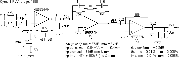
In the Cyrus 2 - 06 the last two opamps were LF353DP. In the 07 and Tog types NE5532N (MC stage here).
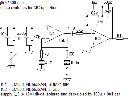
JLHs' K1500 (Hart, Aug '91), a good source of information was found here.
Passively equalised LM4562 version (DC gain 535). This arrangement can reduce negative feedback instability caused by circuit time factors and in some designs the first stage amplifier will have a higher gain than the second and vice versa. Simple component changes can accommodate both MC and MM configurations.
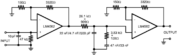
A useful discussion of this approach can be found in the 'Passively Equalized RIAA Preamp Topologies' section (6.24) in 'Op Amp Applications' edited by Walter G. Jung (Analog Devices).
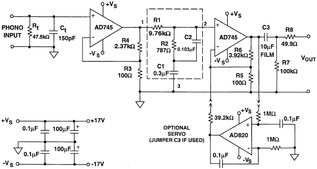
Passive equalisation can offer optimum performance but consideration can be given to LF attenuation by means of AC coupling to cope with record-deck inadequacies since DC is not an RIAA consideration.
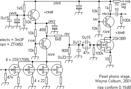
Following on from the complex and expensive Pass Laboratories 'Xono' design, the 'Pearl' offered a reduced price using similar principles and 'no feedback', considered detrimental by some.
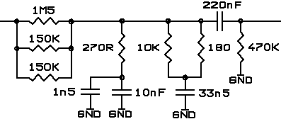
A higher impedance passive network from a Gravesen thermionic design (whose separate supply required 5 mains transformers and a 9H choke)

and another designers' solution.
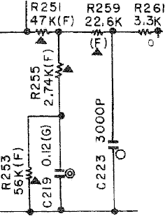
Passive RC network used in the complex Yamaha C-1.
Low component count passive solutions using FET gain stages have been proposed by a number of users.
Preamp supplies
As much attention paid to the amplifier could be applied to the power supply with a useful reduction in noise, eg;
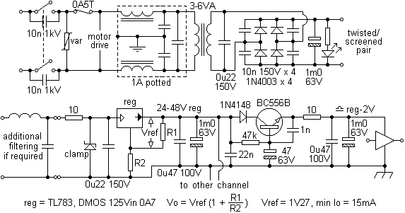
If desired, a thermistor can be placed in series before the mains filter. Notwithstanding generous suppression on the motor drive, a symmetrical rectifier arrangement will produce less transformer noise (B/H characteristics). Zeners on supply rails will effectively clamp spikes if set just above the rail operating voltage. In this case, a 1W device in a pre-regulator position would suffice, thus respecting the regulators' maximum input voltage by a safe margin (spikes being considered a major source of 78L series regulators failures). A design giving a continuous 50mA, with separate hum filters for each channel, should meet most needs, the electrolytic values given being a minimum. A passive load, such as an led, can help reduce high quiescent voltages from a high impedance secondary and in a lot of designs will present the highest load, compared to the preamp. If a mains transformer is to be mounted in a deck, a higher rating than necessary will run at a lower operating temperature. This can increase longevity and reduce the possibility of a hotspot in the deck warping a record left on the platter, say. The transformer should be of a split-bobbin construction or have an earthed screen to reduce mains borne noise.
When increasing a component count 'where there is more to go wrong', increase the components' ratings to reduce failure rates. For example in the supply above, upgrading the 63V caps to 100V types and the 100-150V types to, say, 200V will extend life appreciably, and at pence for years, reducing the need for access.
In order to reduce noise in one custom system, a preamp in a record deck was powered via an existing 5-pin DIN connector (pin 1 = - and pin 4 = +) on the amplifier and the signal returned via the same 4-way individually-screened lead (pin 3 = left, pin 5 = right and pin 2 = ground).
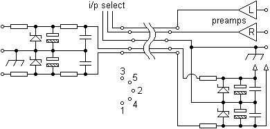
Although considered reasonable at the time, the author holds that in later builds the DIN connector convention should be avoided.
Some 78x/79x series regulators can be very noisy compared to adjustable types like the LM317/37 types, although discrete designs can offer better performance. A post filter of a 10R resistor and a 470µF-1mF electrolytic can help alleviate this. These short-comings led Armstrong to use a relatively simple supply arrangement in their high-end 730 preamp. With audio it is not so important to maintain a precise voltage level as removing and absorbing supply rail noise whether this arises from the supply or the circuitry supplied.
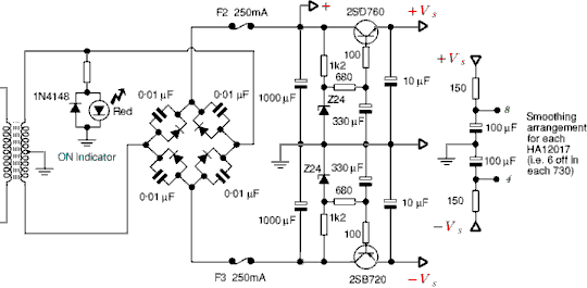
Ceramic caps (0.1µF) paralleled with the electrolytics can do no harm as can similar types across the AC rails. Examples of active hum filters using capacitance multipliers.
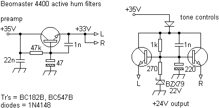
These, although small in cost and component count, can 'lift' an inadequate preamp design subjectively dropping the noise floor significantly.
Moving coil stages
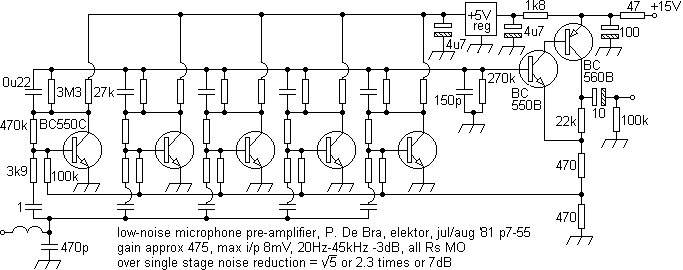
When amplifying low level signals, low noise first stage devices are required. Transformers can offer this but even when screened their susceptibility to hum can overide the advantages given. Below, a moving coil amplifier that caught the eye. This identified the importance of input transistor Rbe in respect of noise performance.
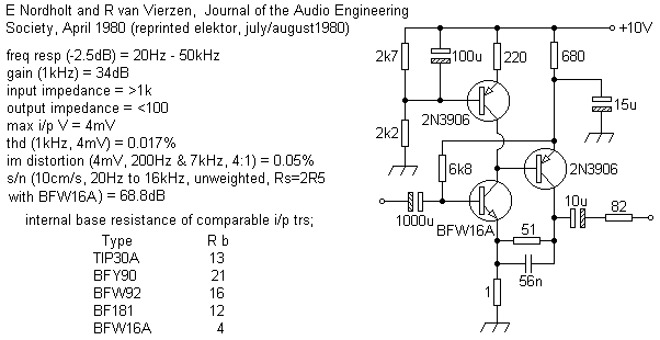
Although transistor types like the BC109C were often seen, others like the 2N4401 offer better performance. A 2N4403 could exhibit an Rbe of 40 when a BC109 gave 400.
Previously, perhaps ten input transistors, and their associated biasing arrangements would have been paralleled (as can be done today with high performance opamps).
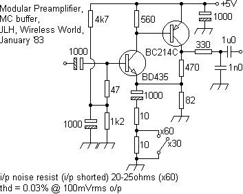
The use of a single medium-power transistor instead, was much more concise, demonstrated by a Linsley-Hood design.
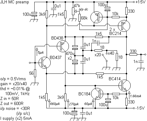
A later symmetrical design intended for low voltage supplies, permissible because of the low outputs involved.
A mic preamp utilised a MJE13007 giving better performance than a BF459, MJE340 or two BF459s in parallel. Noise floors with these types were some 15dB or lower than using a 'standard' low-noise type like a BC549C. The ZTX851 received praise in some circles.
Because of the reduced inductance inherent in an MC cartridge, frequency responses can easily roll-off ultrasonically. For this reason, to reduce the possible distortion that might arise in later amplifier stages as a consequence, an output filter is recommended.
Another interesting approach optimised for an Ortofon MC cartridge.
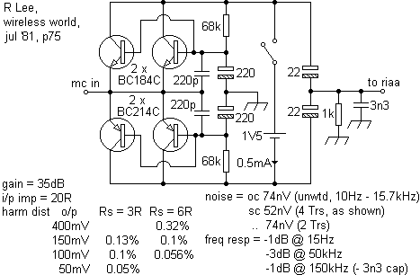
On a practical basis low-noise supplies such as batteries can involve accommodations for charging and switching. Noise arising from mechanical contacts can negate the care taken elsewhere.
This stage was used as the front end of the Cyrus 2s' RIAA stage adding a low-noise dual input pair.
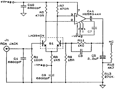
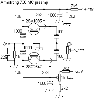
An application from the Armstrong 730 preamp. A similar design was used by Ortofon in one of their MC preamplifiers that was very highly regarded at that time. For the 730 the design was altered to provide a higher headroom level, and slightly better noise and distortion performance. This was followed by an HA12017 RIAA stage.
And another (much later!) version with its' matching RIAA stage.
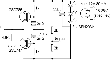
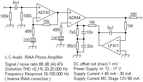
This is literally light-powered in order to isolate the MC stages' supply, the RIAA employing a passive network, current controlling a 60MHz opamp compensation pin, whilst a DC servo looks after offsetting. Elegant, but doubts arise over the bulb supply voltage suggested. High flux LEDs, like those from Luxeon, could be used to increase reliability but whether a bulb filaments' thermal hysteresis aids supply noise decoupling is not known. Bass roll-offs for MM stage at 15Hz and 1.5Hz.
The very compact Technics SL-10 tangential deck which usefully could be powered from a 12V source used the boron-pipe cantilever 310 cartridge which drove the following inbuilt preamp which then fed the following amplifiers' RIAA preamp.
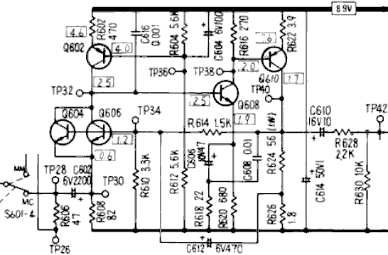
The next design parallels low noise input transistors to sum and help cancel their noise. With an overall gain of 192, the output is attenuated to suit a variety of inputs. A second opamp reduces the DC offset by balancing the amplifiers' input.

A complete MC stage from Huennebeck-Online with plenty of discussion and supporting calculations.
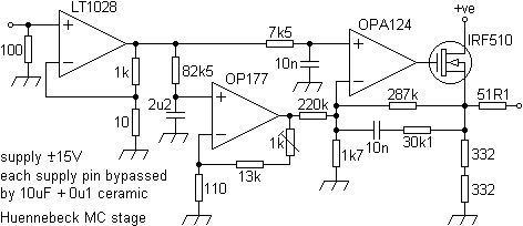
The sound of this design, executed on veroboard, was described as 'cool, sterile and metallic and not that musical'. The inclusion of a class A output stage within the feedback loop of the second amplifier and filter stage using a power Mosfet, apparently gave 'a solution which added the missing characteristics'.
Success was met using MCs to drive gain blocks, such as the ZN459 (x1,000) and later SL561 (var gain), which then fed passive RIAA filters. Such portable low-voltage, low-noise gain blocks were run very successfully from LM2931 (5V) series low dropout regulators fed by a 9V PP3 battery, giving extended supply life. An entire system optimised for 12V operation can provide immense flexibility.
Ultralow-noise opamps, like the AD797, can offer complete single-stage MC solutions. For best results, be mindful of the supply bypassing arrangements suggested in the datasheet. Reducing, for audio, the bandwidth can be beneficial, good screening is also recommended. IC sockets, if used, should be of a high quality (turned pin) but bear in mind that the device dissipation will have to be derated to account for the higher chip-to-ambient thermal resistance.
Reciprocal filters
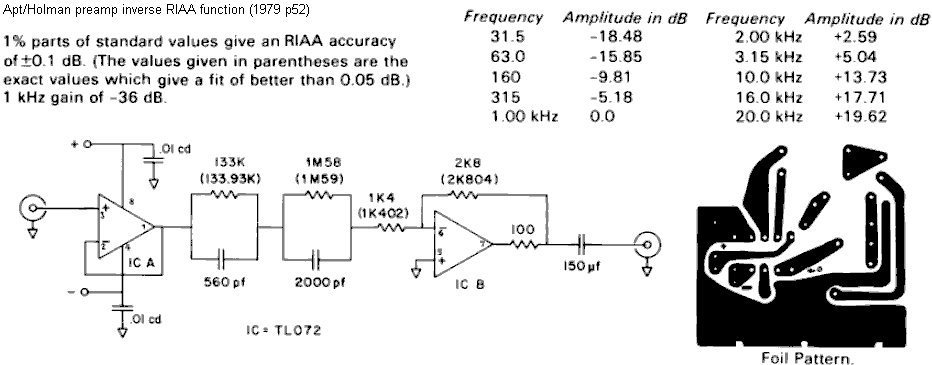
Below are reciprocal RIAA filters to use either for testing RIAA stages or to convert a mag input to a linear one, say, for CDs. Last circuit employs 0.1% resistors, selected capacitors and assumes a load of 47k//100pF.
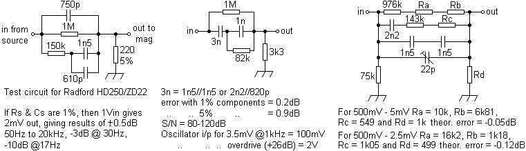
Active circuit for same role.
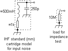
Input load models for testing.
A number of packages are now available where a USB Phono Preamp is accompanied with software to 'clean-up' vinyl outputs providing declickers, decracklers, denoisers, derumblers, dehummers, etc, as can USB record decks, complete with analogue tape outputs.
Another RIAA web-page.
Cartridge specs
Set out below are manufacturers' specs of more than 30 cartridges in use over some 40 years. Experience suggests that the greater difference between different models' specs is indicative of attention having being paid to testing. A low effective tip mass will usually give greater detail as will non-aluminium cantilevers, albeit at a reduced output level. For many years, the Shure V15 Mk3 was held as a standard, often used with LPs like Pink Floyds' 'Dark Side of the Moon' and 'The Wall', and speakers like the KEF 105 Mk2s. The boron-piped Technics EPC-205C Mk3 and the beryllium (sapphire in later types) B&O; 6000/20CL and others like the Empires (boron-coated aluminium) and the later Goldring did very well indeed, all of these types characterised by low effective stylus mass and then high frequency responses, this being the principal development made in cartridge construction over the years.

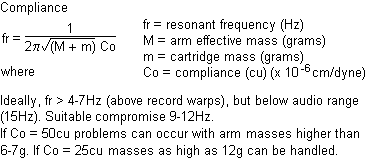
Lighter tracking forces will render greater detail but will also emphasise any arm inadequacies not found in tangential decks. A good compromise can sometimes be found somewhere between the lightest force and the half-way point of the range. In practice, the best value usually proves to be just under the specified maximum. 'Heavy' stylus loadings can suit disco use and high sound pressure environments. However, a record that tracks badly at say 1g, can perform brilliantly at 2g (increase incrementally by, say, 0.25g until best results are achieved), unless the compliance is causing difficulties. A cartridge with a higher compliance needs a proportionately lighter arm and is best used on a tangential deck.
Elliptical styli (about 0.0007 x 0.0003") are usually held to give a better tracking ability than spherical types, the larger dimension being lined across the groove, the smaller dimension tracking more faithfully the smaller, higher frequency waveforms.

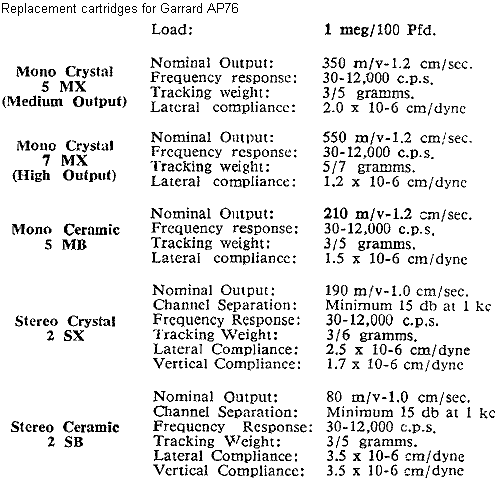
Less expensive ceramic and crystal cartridges are often supplied with sapphire styli to keep prices low. These, however, should be replaced after only about 40 LP sides. Harder diamond types can give a playing life of 2,000 LP sides before inspection is required. The Garrard Zero 100SB had an 'Automatic Record Counter' set in its' perspex yoke. Cheaper grade diamond styli may not be as precisely cut or polished than full price equivalents. Some can be the proverbial rusty nail in a plank and cause much damage.
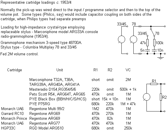
See also Philips 624A.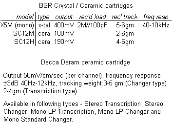 This last cartridge (stereo transcription) was used in the Decca RP205 and, below, a later design.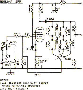
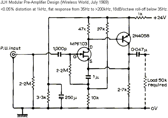
Linsley Hood impedance converter stage for ceramic cartridges (later preamp designs). The steep low roll-off acknowledges the high rumble found in decks of this (and later!) age.
'Ceramic Pickup Equalization' by B. J. C. Burrows (Wireless World, July '71) is a useful source of information and is recommended.
Other types could interest like the Euphonics Miniconic cartridge (1966?) whose crystalline silicon elements received a polarising current from an external power supply which some enthusiasts would modify to reduce ripple. A complete system had the PSU built into the amplifier section. With an elliptical stylus and low tracking weight the Miniconic gave an excellent bass response, output was adjustable between 8mV/47k (RIAA) and 400mV/500k (flat). This cartridge was used by Jabez Gough to demonstrate his speaker design.
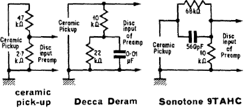
Some practical advice from the Sinclair Stereo 60 manual (which omitted pi from its' reactance equations).
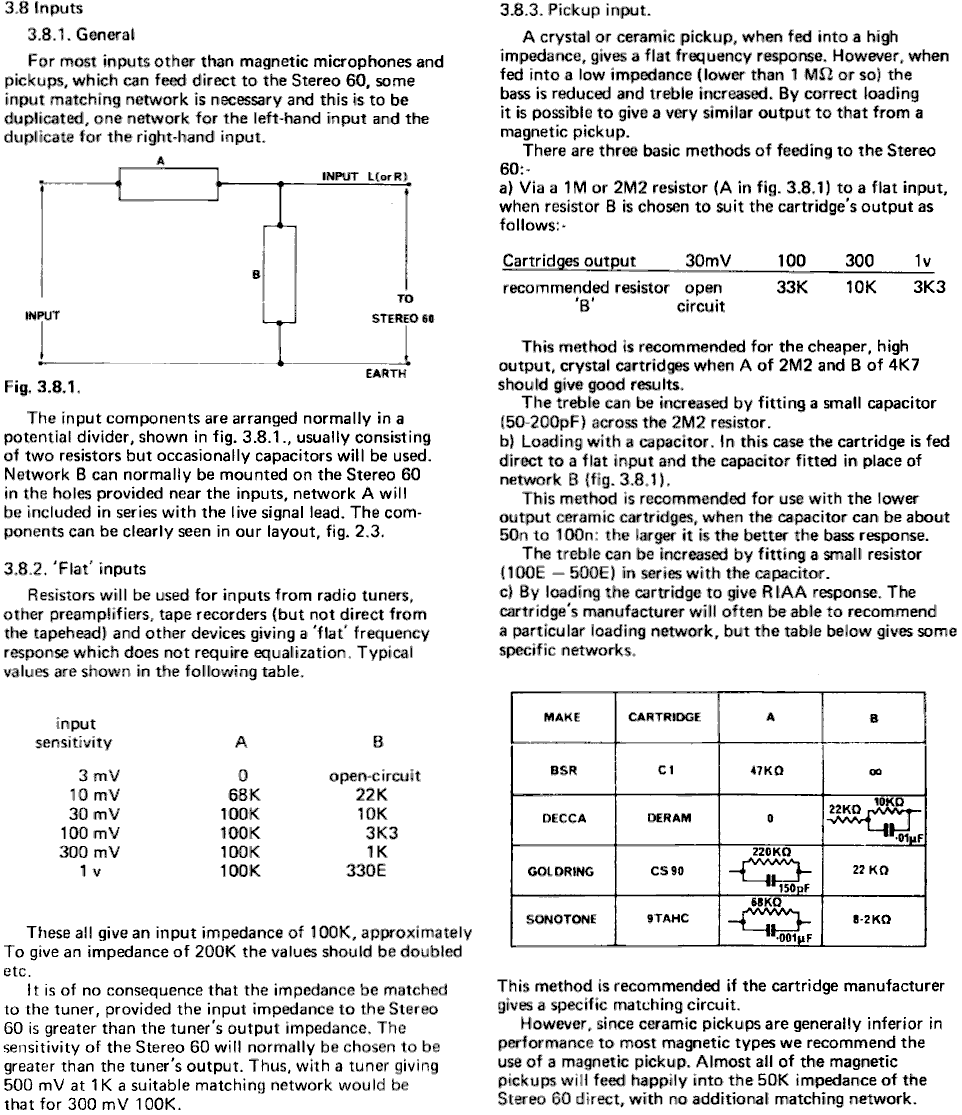
Pre-RIAA loadings for the ('75) Orion, note differences between recommendations.
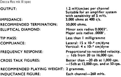
The qualities of early magnetic cartridges were limited and performance varied between batches, not only in respect of frequency response but with crosstalk too, notably through variations in inductance. To put the technology into perspective, Dinsdale found that using a Decca "ffss" MkI cartridge with a Decca SXL 2057 test record produced a channel difference of only 6dB @ 2kHz when only one channel contained recorded information. His approach addressed the problem by using a high input impedance (100k). Later types gave an improved spec.